Odometry is the use of data from sensors to estimate changes in position over time. It is used in robotics to estimate the robot’s position relative to a starting location. In wheeled robots, this is often implemented using wheel encoders, which can measure how far the wheels have rotated, and paired with knowledge of the dimensions of the wheel, can be used to estimate odometry.
Although wheel odometry is the most commonly used in mobile robots, other sources of odometry exist. One fairly common one is visual odometry, which uses sequential camera images to estimate the distance traveled. The main idea is to match key points between subsequent images and compute a transformation between them. The transformation determines how much we have moved and rotated.
In this article, and continuing my experimentation with LiDAR point clouds, I discuss a very simple experiment to obtain LiDAR odometry. The idea is similar to that of visual odometry, except that instead of trying to match key points between two subsequent images, we try to match points from two consecutive point clouds. To achieve this, we can use a technique called point-cloud registration or scan matching.
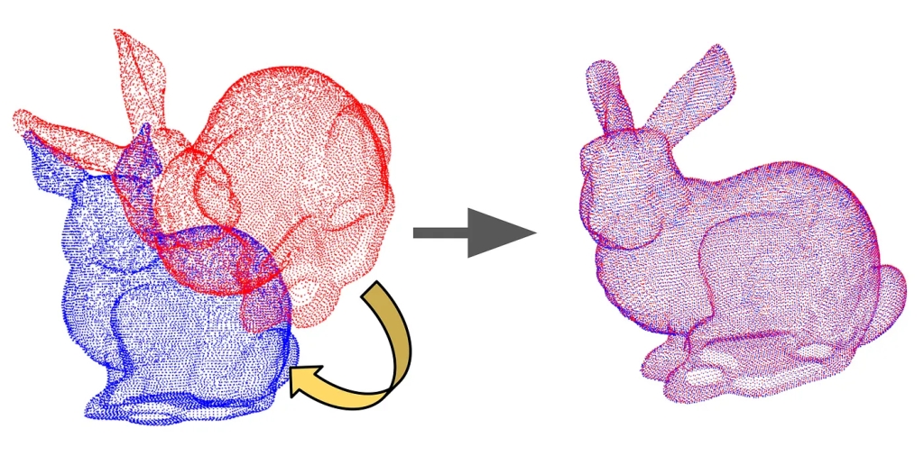
Point-cloud registration or scan matching, is the process of finding a spatial transformation (scaling, rotation, and translation) that aligns two point clouds. In our case, since the point clouds come from the same LiDAR source, we are not concerned with scaling. There are multiple ways to implement scan matching, but one of the most used techniques is called the Iterative Closest Point algorithm (ICP).
The goal of ICP is to minimize the difference between two clouds of points. It iteratively refines the transformation required to align the source cloud to the target. ICP is often used to reconstruct 2D or 3D surfaces from different scans, but also to help localize robots (especially when wheel odometry is unreliable due to slippery terrain).
Given that our LiDAR is fixed to the robot, the rotation and translation from one point cloud to another obtained from the scan matching algorithm is a good indication of how much our robot has moved and rotated. There are different flavors of the ICP algorithm, depending on which metric it has to minimize. I tried the Point-to-Point and the Point-to-Plane variants, with the latter giving much better results.

Below is Python code that is part of a Robot Operating System (ROS) node that takes care of computing the transformation using Point-to-Plane ICP. The code uses the Open3D library for point cloud processing. First, it estimates the normals from the target and source. The normals are used to define the planes to which the points are to be aligned. Then it performs the point cloud registration (or scan matching) using the registration_icp() function from Open3D.
The point cloud registration function is defined as follows:
open3d.pipelines.registration.registration_icp(source, target, max_correspondence_distance, init, estimation_method, criteria)
In my code, the max_correspondence_distance is set to 1.0 through the threshold variable. The init parameter is the initial transformation estimation, which if not provided defaults to the identity matrix. In my code, I use a variable named transformation that starts as the identity matrix but is later replaced by the latest transformation returned by the perform_icp_point_to_plane function.
def perform_icp_point_to_plane(self, source, target):

    # Estimate normals
    o3d.geometry.PointCloud.estimate_normals(
        source,
        search_param=o3d.geometry.KDTreeSearchParamHybrid(radius=1, max_nn=30))

    o3d.geometry.PointCloud.estimate_normals(
        target,
        search_param=o3d.geometry.KDTreeSearchParamHybrid(radius=1, max_nn=30))

    threshold = 1.0  # Distance threshold
    trans_init = self.tranformation #np.eye(4)  # Initial transformation

    # Perform point-to-plane ICP
    reg_p2p = o3d.pipelines.registration.registration_icp(
        source, target, threshold, trans_init,
        o3d.pipelines.registration.TransformationEstimationPointToPlane())

    return reg_p2p.transformation, reg_p2p.inlier_rmse
Finally, once you have an estimated transformation, you multiply it with the previous odometry to obtain the updated odometry. The starting odometry can be set to the identity matrix or can be initialized with the value of the wheel odometry of the robot.
self.transformation, inlier_rmse3 = self.perform_icp_point_to_plane(self.prev_cloud, cloud)
self.odometry = np.dot(self.odometry, self.transformation)
The general algorithm is as follows:
odometry = identity or another source
transformation = identity
prev_cloud = initial point cloud
repeat
  cloud = read point cloud
  transformation = perform_icp_point_to_plane(prev_cloud, cloud)
  odometry = odometry⋅transformation
  prev_cloud = cloud
The following video demonstrates this basic LiDAR odometry and compares it to the default wheel odometry of my robot. The demonstration showcases how LiDAR odometry can be more robust than wheel odometry under specific scenarios. The robot in this demo navigates through a highly structured environment before returning to its original starting point. When the robot moves slowly, the LiDAR odometry proves to be very accurate. However, for faster motions or more unstructured environments, a more sophisticated and robust LiDAR odometry approach would be necessary to maintain this accuracy.

Leave a comment